


 русский
 Español
 Deutsch
 عربى
عربى
Home / News / Industry News / Pressure Drop Behavior in Male Tube Teeth Hose Adapters Under Real Flow Conditions
Industry News


Pressure Drop Behavior in Male Tube Teeth Hose Adapters Under Real Flow Conditions
 2026.07.24
 Industry News
Content
- 1 Understanding Pressure Loss Inside Tube Teeth Adapters
- 2 How Tube Teeth Structure Influences Water Flow
- 3 Pressure Drop Changes Under Different Operating Conditions
- 4 Thread Design Impact on Hydraulic Performance
- 5 Material Selection and Pressure Stability
- 6 Testing Pressure Drop Performance in Real Applications
- 7 Practical Ways to Reduce Pressure Loss
- 8 Final Perspective on Tube Teeth Adapter Flow Behavior
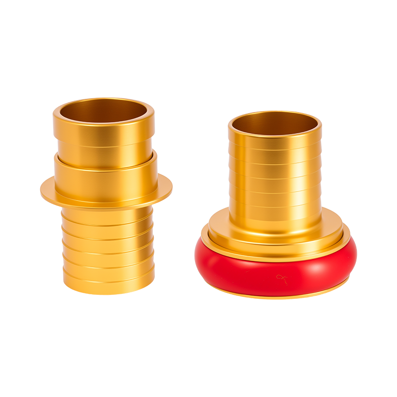
Water transfer systems often depend on small connection components that appear insignificant compared with pumps, valves, and hoses. However, a compact fitting can influence overall hydraulic performance, especially under continuous flow conditions. A Male Thread Tube Teeth Adapter combines threaded connection structures with tube gripping mechanisms, creating multiple internal transition zones where pressure changes may occur.
Unlike straight hose sections, adapters introduce changes in flow direction, internal diameter, and surface geometry. These changes create additional resistance that affects pressure stability, flow velocity, and system efficiency. Studies on push-to-connect fittings show that pressure losses are closely related to fitting geometry, internal flow paths, and Reynolds number variations.
Understanding Pressure Loss Inside Tube Teeth Adapters
Internal Geometry Creates Flow Resistance
A hose system does not lose pressure only because of hose length. Connection components also contribute to energy loss. Inside a tube teeth adapter, water passes through several structural areas:
- Thread transition section: The connection area between the external thread and the adapter body may change the internal passage.
- Tube gripping zone: Internal teeth create contact points that may slightly disturb the water pathway.
- Sealing chamber: O-rings or sealing elements may reduce the available flow area.
Pressure drop in fittings is usually associated with changes in flow direction, velocity, and cross-sectional area rather than simple friction along a straight pipe.
Flow Area Reduction Near the Adapter Core
A common reason for pressure loss is the difference between the hose inner diameter and the adapter internal passage. Even a small reduction in flow area increases fluid velocity and creates additional turbulence.
| Adapter Condition | Flow Effect | Possible Result |
| Large internal passage | Lower turbulence | Stable water delivery |
| Narrow transition zone | Higher velocity change | Increased pressure loss |
| Uneven internal surface | More turbulence | Flow fluctuation |
How Tube Teeth Structure Influences Water Flow
Grip Performance and Flow Performance Balance
The internal teeth of a tube adapter provide mechanical retention by gripping the inserted tube surface. The teeth must create enough holding force without excessively disturbing the internal passage.
- Sharper teeth improve tube retention but may increase internal deformation near the connection point.
- Longer gripping sections improve stability but may reduce available flow length.
- Incorrect tube insertion depth changes the designed flow path.
Push-to-connect fitting designs typically rely on a combination of an O-ring seal and gripping teeth that hold the tube after insertion. The internal arrangement of these components determines both sealing reliability and hydraulic behavior.
Tube Deformation Around Tooth Contact Areas
Flexible tubing can slightly deform after being locked by internal teeth. This deformation may create an uneven internal surface, causing localized turbulence.
The effect becomes more noticeable under:
- High flow velocity applications
- Long operating periods
- Soft tubing materials with lower stiffness
Pressure Drop Changes Under Different Operating Conditions
Low Flow Applications
At lower flow rates, the pressure difference across a Male Thread Tube Teeth Adapter is usually limited because water moves through the fitting with relatively low velocity.
Typical applications include:
- Small irrigation systems
- Water filtration connections
- Low-pressure fluid transfer equipment
The influence of internal geometry exists but may not significantly affect overall system performance.
High Flow Applications
Higher flow rates create stronger velocity changes inside the adapter. Turbulence increases around thread transitions and gripping sections, producing greater pressure loss.
| Flow Condition | Adapter Response | Main Concern |
| Slow water movement | Minor resistance | Limited pressure variation |
| Continuous medium flow | Stable resistance increase | Gradual pressure reduction |
| Rapid flow demand | Higher turbulence | Noticeable pressure loss |
Thread Design Impact on Hydraulic Performance
External Thread Connection Does More Than Provide Attachment
The male thread section connects the adapter with valves, pumps, or other hose components. Although threads are outside the main water passage, poor design alignment can influence the internal transition between components.
- Incorrect thread matching may create assembly gaps.
- Excessive tightening may distort sealing components.
- Poor machining accuracy may affect flow alignment.
Thread Standard Differences Create Connection Challenges
Male threaded adapters may use different standards, such as NPT, BSP, or other regional thread specifications. A connection that appears compatible externally may create internal alignment problems.
| Thread Issue | Flow-Related Effect |
| Wrong thread specification | Improper sealing position |
| Incomplete engagement | Connection instability |
| Excessive tightening | Component deformation |
Material Selection and Pressure Stability
Metal Adapter Body Performance
Tube teeth adapters are commonly manufactured from materials such as brass, stainless steel, or engineering plastics. Material choice affects machining precision, surface finish, and long-term dimensional stability.
- Brass: Commonly used due to machinability and wear resistance.
- Stainless steel: Suitable for applications requiring stronger corrosion resistance.
- Engineering plastic: Provides lightweight construction for selected applications.
A smoother internal surface reduces disturbance to water flow, while accurate machining helps maintain consistent passage dimensions.
Seal Material Affects Long-Term Flow Behavior
The sealing ring inside the adapter must maintain contact pressure during operation. Aging, temperature changes, and repeated connection cycles may influence seal deformation.
- A worn seal may create internal leakage paths.
- A deformed seal may reduce effective flow space.
- Incorrect seal material may change under temperature variation.
Testing Pressure Drop Performance in Real Applications
Key Testing Factors
Laboratory testing and practical field evaluation usually consider several parameters:
- Flow rate measurement before and after the adapter
- Pressure difference across connection points
- Water temperature and viscosity changes
- Tube material and insertion condition
Testing methods for fittings commonly measure pressure distribution before and after connection components to understand hydraulic resistance.
Practical Ways to Reduce Pressure Loss
Improve Connection Design Matching
- Match adapter internal diameter with hose size.
- Avoid unnecessary reducers in high-flow systems.
- Use compatible thread standards.
- Maintain correct tube insertion depth.
Consider Flow Requirements Before Installation
A compact adapter may perform well in a small water circuit but create measurable resistance in a high-volume delivery system. Understanding expected flow conditions helps users balance connection convenience with hydraulic performance.
Final Perspective on Tube Teeth Adapter Flow Behavior
A Male Thread Tube Teeth Adapter influences water system performance through several internal factors, including flow passage design, gripping structure, sealing arrangement, and thread alignment. Pressure drop is not caused by a single component feature but by the combined effect of mechanical and hydraulic conditions.
Evaluating adapter design under realistic flow conditions allows users to build hose networks with more stable pressure performance and fewer unexpected flow restrictions.
Related Products


-
 (+86) 18968568369
Give Us A Call
-
 [email protected]
Drop Us a Line
-
 No. 32, Mechanical and Electrical Industrial Park, Donghai Avenue, Yuhuan City

Zhejiang Taizhou Honghe Technology Co., Ltd. is an emerging enterprise focusing on the research and development, production and sales of fire fighting equipment.
© 2025 Zhejiang Taizhou Honghe Technology Co., Ltd.
Storz Coupling & Firefighting Equipment Factory
